
After checking the total distributor advance with a friend, we went on a test drive and it seemed like the tachometer might have been in need of an adjustment. I then set out to try and get it as accurately calibrated as possible and refurbish it as much as I could at the time. I made sure to take lots of pictures. Lets begin by looking at how the wires are connected at the back of the unit.
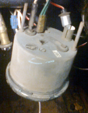 In this picture we see that there are three connections at the back. On the left is a white wire with a "bullet" style connection. This is the signal wire that can be traced back to the low tension lead on the coil. It actually has two connections with the unit but the other one is obstructed by the green wires in the picture. Next is a green wire which connects to power on the fuse block. On the tachometer it uses a spade connection. The red and white wire has a lightbulb socket on this end which simply slides into the unit and connects to the rest of the dashboard light circuit. There is also a black wire that connects to one of the two threaded posts for ground. According to the bentley manual, this is how the tachometer is hooked up on all cars from G-AN5-74886 to 105500 (1969-1971 production year). The earliest tachometers used on spridgets were mechanical and connected to the generator with a spinning cable. This is one of a few types of electric tachometers used. If another type come into my hands I will detail their construction and operation too.
Lets look at the front and back of the unit.
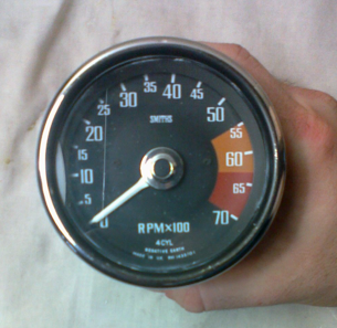
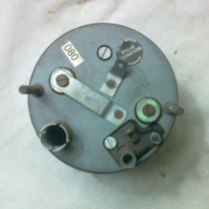
In the front, we see the chrome bezel, crystal, light reflector ring, face and needle. More on that later. The back features the aforementioned electrical connectors and one that is not used here. The spade connector in the upper left that is riveted to the casing is a ground connection, but from '69-'71 the mounting posts were used instead. Also visible is a sticker in the upper left that seals over the calibration potentiometer. To remove the tach from its casing, gently twist the bezel until the tabs align with the slots on the front of the unit. It should come off easily. Now unscrew the two flat head screws on the back that have washers under them.
Now lets look more closely at the bezel assembly
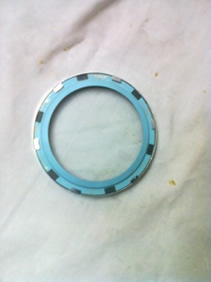
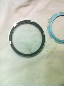
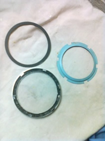
Disassembly proceeds as follows from left to right. First the reflector ring is twisted until it can be removed, then the paper shim, and finally after carefully bending back the tabs, the crystal (as shown bellow).
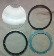
The chrome bezel appears to have had some kind of rubber sealant inside from the factory. The closest approximation is probably black silicone. In my car it had become very hard and brittle after 40 some years, and was very difficult to remove. Without the addition of black silicone, the crystal tends to rattle around inside the bezel and can cause the driver some degree of irritation.
The inner half of the chrome bezel on some years is painted flat or semigloss black. It is terribly difficult to properly mask, I have found a good workaround. You can find it here along with instructions on how to refinish the rest of the unit.
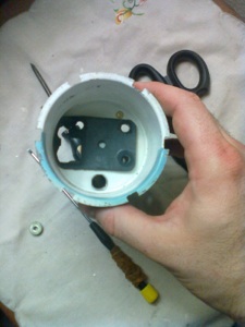
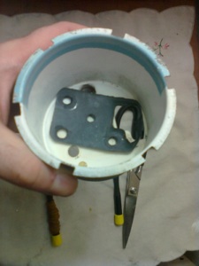
Now on to the rest of the disassembly. With the bezel off and the case removed, I suggest that you take the time to inspect the inside of the case. At the back is a moulded rubber insulator that prevents the unit from being shorted to ground. Only one of the two screws holding the case on is grounded to the body and both screws must pass through this rubber piece. Dry rot may well have taken hold of this so when you remove it do so with the utmost care so as to avoid damaging it. I don't know of any place that sells a replacement.
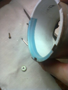
You may also notice that the paint has started flaking and cracking on the inside from years of being close to a light bulb. If so (as it is here) it's time to strip off the old paint and refinish it. I can't quite explain why there is a blue stripe around the bottom of the case, but I tried to reproduce it as best as I could. All I do know is that on both my tachometer and my speedometer, the half with the lightbulb in it is the half with the blue stripe.
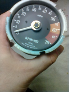
Now lets examine the unit outside of its case.
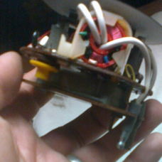 On this side we see that the white signal wires wires wrap around an induction coil twice. This coil has two sets of windings. The secondary set on the bottom is connected to the calibration pot shown here with a yellow knob. Presumably turning the pot changes the sensitivity of the unit to the signal from the coil.
Notice that one bullet connector is female and the other male, this is to avoid getting the signal wires crossed upon installation.
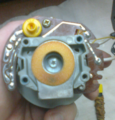
If we carefully remove the bottom circuit board, we can see a pole piece, and the upper circuit board. The circuit board was probably etched and then the copper coated with solder to prevent corrosion. Its a pretty simple design.
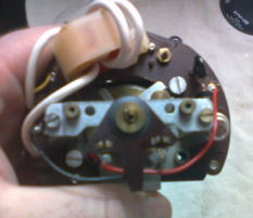 The face is easily removed by undoing the two screws on the face. However some care is needed when removing the needle. The face is easily scratched by prying it off from the front of the face, but if you stick a small screw driver under the face and pry it off from there, it should go smoothly without leaving any noticeable damage.
Here we see the front with the face removed. Reassembly is the opposite of disassembly :)
~Seth Jones