
While working on the tachometer I decided to take a look at the speedometer. As with the tachometer  the bezel twists off and is easily broken down into 4 parts. Info on how that is done can be found here.
Anyhow on the front we see a blue stripe painted on the inside of the case but this time it is in the upper left side rather than on the bottom as with the tachometer. I can't quite explain why there is a blue stripe around the upper left side of the case, but I tried to reproduce it as best as I could. All I do know is that on both my tachometer and my speedometer, the half with the lightbulb in it is the half with the blue stripe.

On the back we see the light bulb socket holder, the connection for the trip reset cable, and the speedometer cable. In this picture the two Screws and their washers have already been removed. They are all that holds the mechanism in the case.
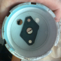 As with the tachometer there is a moulded rubber spacer that electrically isolates the inner workings of the device. In this case however it seems like it serves more as a source of shock absorbsion than electrical insulation since the speedometer is mechanical. The only electronic part in this unit is a light bulb. The hole for the light bulb is seen in the upper left of this photo.
The paint on this one looked especially bad
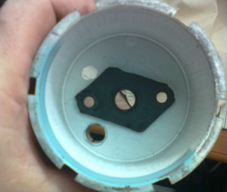
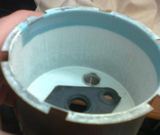
It was actually flaking off in small pieces and left white flecks all over the face and on the inside of the
crystal. When paint gets like this you have to strip it off and start over. Details on how that is done can be found here.
But now lets take a look at the mechanism.
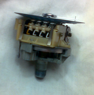 |  |
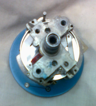 The heart of the unit can be seen from the back. The speedometer cable connects to a magnet which spins very close to a metal disc. This converts the spinning motion of the cable into torque. Acting against the torque are some return springs. So basically, the faster you drive the more toque is applied to the return springs and the further the needle moves. The needle is best removed by placing a finger on the metal disc and carefully twisting the needle off (reinstall the same way and make sure that the needle points to a black mark on the metal disc).
Some degree of calibration is possible. If your speedometer consistently reads a set amount too slow or too fast, you can change the alignment of the needle to the disc to read up to 15 mph faster and more than 15 mph slower. If the speedometer is adjusted to read more than 15 mph faster it will never completely return to zero. Setting it too fast can also bend your return spring. If you set your speedometer too slow, two things can happen. First you risk weakening the return spring, and second, the force of the return spring wound up so tight will cause the unit to lose it's calibration when the needle hits the stop at 0.
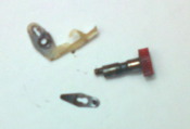
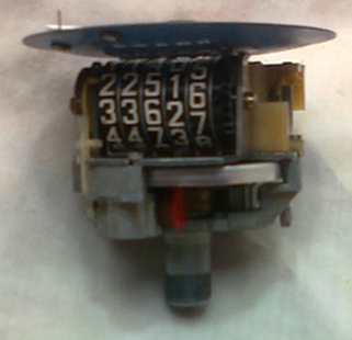
Like most speedometers in cars, this unit features an odometer and trip counter. These are powered by a worm gear which turns a tooth red plastic gear at a ratio of 32:1 (shown here in the top and rear views). This red plastic gear is permanently fixed to a well greased axle. The opposite end of the axle features an eccentric shaft 1/2 the diameter of the axle. The ratcheting arm slides into place over this shaft and is held in place by a specially made spring clip.
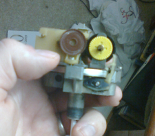
This means, when the red gear turns,the eccentric shaft causes the ratcheting arm to move forward (pushing against a brown 43 tooth ratcheting gear), advance the odometer slightly, and then move backward to engage the next tooth on the ratcheting gear. One full rotation of the input shaft of the odometer is a measurement of one mile. If the car moved backward, the ratcheting arm moves away from the brown gear and will not cause either the trip counter or odometer to lose mileage.
 |
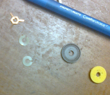 |
The brown gear itself is held onto the odometer input shaft by a plastic circlip and a copper spring. The spring is there so that the brown gear ratchets against a nonrotating yellow plastic wheel. This further safeguards against the odometer from losing mileage. The odometer shaft is located by a second plastic circlip as well as the spring and the previously mentioned circlip. If the inner of these circlips fail (and it has have failed on my car before) the odometer will cease to function, even though the speedometer still reads the correct speed.
The Odometer is made up of a series of numbered wheels with metal plates and small yellow pinions sandwiched between them. They all slide onto a brass bushing and are kept in alignment by tabs on the end of the metal plates as shown below.
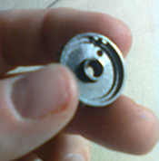
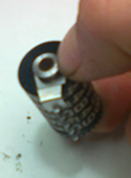
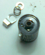
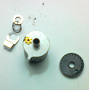
The alignment of the wheels with the pinions is critical. Holes are drilled in the numbered wheels to aid assembly at the factory where the mileage is set to 0 by default. However, if you are servicing your unit, or you are changing speedometers and want to make your new speedometer display the correct mileage, then these holes will not help you much at all. Instead, add wheels one at a time so that the correct number reads opposite the metal tab on the plate. Then check to make sure that the previous wheel advances the one you added when the previous one reaches 0. If it doesn't then remove the wheel you just added and the metal plate and rotate the yellow pinion 60º in either direction.
The trip counter is located by the reset pinion on the end of its axel and by the input shaft which connects to the reset cable. This input shaft has a yellow plastic pinion on one end, and a metal circlip on the other. To remove the trip counter, remove this circlip, slide out the input shaft (the yellow pinion will fall off), and then slide the trip counter's axel out. There is a pinion that connects the trip counter to the odometer. It is riveted to the unit and cannot be removed.
Unlike the odometer, the trip counter does not have any metal plates and the pinions are located outside the numbered wheels. This is because the wheels have to be able to ratchet independently from the odometer and have to be able to reset back to 0. As with the odometer, alignment is critical. Unlike the odometer however, setting it to 0 is always preferable and this makes the process much easier. Still be sure to test the reset function and also make sure that the wheels all advance at the proper time once you put it back together.
~ Seth Jones