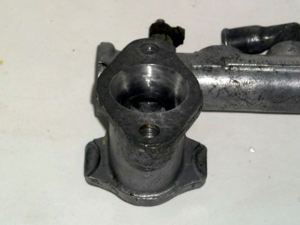
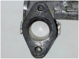
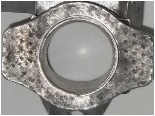
David Vizard makes brief mention of how to accomplish this in his book on Tuning the A-Series engine. Much of his time is devoted to which singe carb manifold is preferable. When he does get around to mentioning twin S.U. manifolds, all he says about the standard factory item is that it is perhaps the worst design as far as flow is concern of any of the manifolds he's tested. He also says that this can be much improved by porting. Porting is all about making the crooked straight, and the rough places plain.
Since I have a dremel, more time than money, and a spare manifold to mess with I thought I'd give it a try. The first thing I noticed was that the diagram Vizard uses must have been for a different casting. Given that most of the book focuses on transversely installed A series engines, I would guess that the casting so diagramed is for a mini. This would explain why his manifold is shorter, and sets the carbs at a steeper incline.
I have come up with a cross sectional diagram of my own. But as I am unwilling to saw one of these manifolds in half, I cannot guarantee 100% accuracy of the internals, but it is good enough to give you a general idea of what is going on.
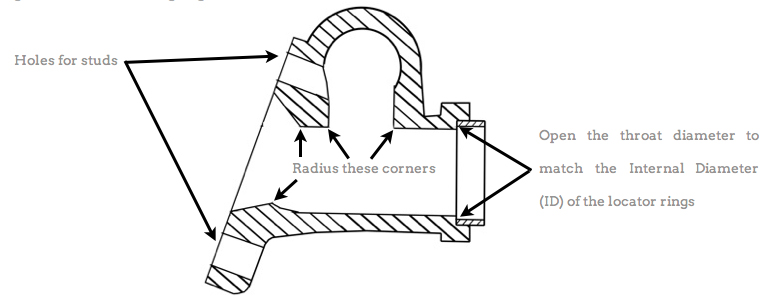
The diagram shows the manifold roughly as it is in standard trim along what should be done to it to improve flow. In Vizard's book it suggests that the problem with the mini manifold is that the locator rings are smaller than the throat. Here we have the opposite problem, the throat is smaller than the ID of the locator rings. You may also notice a line down the sides of the throat. This is left over from a slightly misaligned joint in the mold for the casting sand and can here serve as a guide to how much material you've removed.
It is clear to me that the design of the 12G1451 I'm working with here had more to do with lowering cost of mass production than anything else. The cross tube was apparently counterbored on each end of the cross tube. The cross tube was also drilled from the top to provide ports for emissions equipment and also to accept a stud for holding the heater return pipe. Then the carburetor side would have been drilled and tapped for studs as well as given a tapered counterbore so that the manifold's ID would transition to the ID of a 1 1/4" SU. Finally the engine side was counterbored to accept the locator rings. I am told that there is an earlier variant of this casting that had a smaller port connecting the main throats to the cross tube and that the smaller ports make porting more successful in boosting horsepower.
The advantage of counterboring the carb and engine sides in this way helps ensure proper alignment and ease of assembly first and foremost. However you have one resource that the factory did not. You have time to go in and round off corners, and port match etc. The more you can increase the ID of the manifold's throat the better it will flow. Some racers even remove the locator rings all together and increase the throats diameter until it matches that of the counterbore on the engine side! However I have ben told that this is unwise on a street motor.
The first step is to remove all the studs, and bolts and whatever else may bee attached to the manifold. You will want to have everything out of the way so That you can easily move your tool to whatever angle you need. I used the good old double nut method, but if you have a stud extractor, go for it.
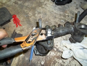
Next I recommend degreasing it as much as possible. Its a lot more pleasant to work on a clean part than one covered in grime. It might even be safer.
There are a number of options as far as tools that may be used to port the manifold. I began this job on thanksgiving day when I was away from my apartment in wheaton, so i didn't have access to my dremel. I was able to borrow someone's drill press and the rasp bit pictured below was handy.
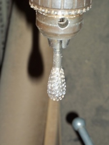
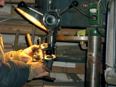
The drill press didn't move fast but the bit was fairly aggressive so it was easy to remove the unwanted material. I also liked that I could hold the work with both hands as well as the conveniently placed lamp making it easy to see what I was doing. The down side is that it couldn't reach all the way down the throat. When I got home I got an 80 grit flap wheel for my dremel (which starts out at just slightly larger than the throat of the manifold so its a good fit). Using the flap wheel I was able to do the second throat relatively easily. I actually prefer using the flap wheel to the drill press because it doesn't leave aggressive gouges in the piece that would need to be smoothed out with sanding.
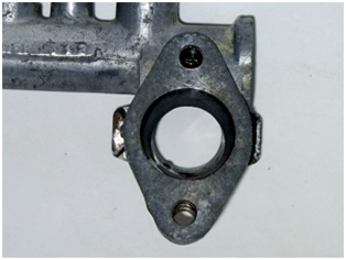
The dremel was able to go about 3/4 of the way through the piece which gave me better access. once you have made sure that everything has a nice contour, leave a somewhat roughed up finish with 80 grit sandpaper. Thats another reason why I liked the 80 grit flap wheel. You don't want the surface as smooth as glass because then the fuel will stick to the sides and it wont flow as well as if its a little rough. Its kind of like the reason why golf balls have dimples. Sometimes a little turbulence is a good thing As I don't have a flow bench and am too poor to spend money on a dyno, the before and after pictures are all I can give at this time. However, a friend who races MGB's said that it looks good and that I was on the right track. I will post figures as soon as I can afford them.
Before
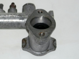
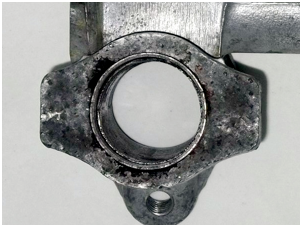
After