
Introduction
This article is the story of spridgets bound for North America, a company trying to keep exporting to its biggest market, and the North Americans who love these cars. If you have a car originally sold in another part of the world, please keep this in mind. Much of what follows comes from Harold T Glenn's 1968 Automotive Smog Control Manual, with additional material from parts catalogues, Terry Horler's Original Sprite and Midget, Anders Clausiger's Sprites And Midgets: The Complete Story, Wikipedia, and autolife.umd.umch.edu
The Story
Laws and attitudes about air pollution have changed over the past century. By now smog has become a rare occurrence if it happens at all. This was not so in the mid 20th century in major metropolitan areas. The problem was caused when hydrocarbons and nitrous oxide under went a photochemical reaction creating a noxious cloud of polluted air which could become trapped by atmospheric conditions (such as low wind and temperature inversion layers). In some cases, such as an incident in 1948 in Donora Pennsylvania, smog resulted in many deaths. The problem was especially bad in Los Angeles, and as a result California would lead the way in emissions control legislation.
Restrictions were placed on many sources of pollution without any effect on the smog problem before attention was turned to automobiles. By the time the very last Bugeye left Abingdon, all cars sold in California were required to have some sort of crank case emission control as standard equipment. On the Bugeye this was a simple breather pipe that ran from the valve cover to the air cleaner on the forward carburetor that recirculated blow by gasses into the carbs. Over time, these systems grew more and more complex as ever more stringent legislation was passed in the USA.
The passing of the 1967 Air Quality Act, as well as the Safety Act of 1966 meant that special North American models would begin production on November 1967 for the 1968 model year. In 1968 (1966 in California), allowable exhaust emission levels were set at 275 parts per million (ppm) for hydrocarbons and 1.5% by volume for carbon monoxide. To meet the new standards a whole new laboratory building was constructed and a test program launched at the cost of more than £60,000. One casualty of this new legislation was the Big Healey. British Leyland reasoned it would not have been cost effective to redesign the car to meet the new standards. A secondary casualty may have been the Austin Healey name, since attempts to replace the BJ8 AH3000 left the relationship between the Healey family and BL management increasingly strained.
1970 saw the addition of amendments which would demand strict controls on evaporative loss emissions from carburetors and fuel tanks (the 1970 goal was 180 ppm for hydrocarbons and 1.0% for carbon monoxide). At the same time from 1969 on, ever greater emphasis was placed on controlling pollution from automobile exhaust. At first this meant adding Air Injection Reactor (AIR) systems to both Sprites and Midgets. According to Terry Horler's Original Sprite and Midget, from November 1967 to August 1970 (Oct 1969 in California) engines so equipped had engine numbers beginning with the prefix 12CD-DA-H. From August 1970 (Oct 1969 in California) to August 1971, engines began with 12CJ-DA-H which included a more sophisticated evaporative loss control system. Further restrictions led to the reduced compression ratio 12V 587 ZL engine from August 1971 to August 1972, when the prefix changed to 12V671 ZL for the rest of 1275cc midget production. The catalytic converter was under research as early as 1967, and legislation was passed that would make such devices required equipment for 1975. However, lobbying managed to push the deadline back to 1977, and with car 188001 a catalytic converter became standard equipment for all Midgets bound for North America.
The opinion of all of these events among british car owners is usually quite low and not undeservedly so. In many states these cars would be subjected to continual emissions testing long after the factory closed. Many times this meant that an owner would tune his car just to beat the test, limp to the testing station, then put everything back to the way he had it in the parking lot and race his now polluting car home afterwards. I was forced to hand the keys over to technicians unaccustomed to the finer points of operating a 30 year old car who found themselves at a loss as to how to start the car, or even stop it. At the time the rear brakes wouldn't work and the ignition lock was worn. Controversy surrounded the possible excessive wear on drivetrains caused by the use of a rolling road.
In illinois the laws weren't adequately taught to all technicians, either. My MG Midget should have only been tested at idle as the laws in effect for 1970 required, however it was always put on the rolling road. It was once failed for having a dirty exhaust cap which I then cleaned with a little spit and elbow grease, after which it passed after some argument about wether it was the same cap or not.
By 2009 in Illinois, the law changed so that MG's no longer have to be regularly tested. By now the technology in most of the cars on the road has advanced to the point where they have a much lower impact on the environment than they once did. Smog is hardly ever an issue and attention has turned to reducing carbon emissions instead of hydrocarbon emissions. Many owners quickly remove all the "smog equipment" as soon as they have the chance. Not every state allows that freedom. On some of the later cars there is great benefit in doing so. The North American bound 1500 Midgets were (in this writers opinion) severely limited by the single Zenith-Stromburg carb and the automatic choke used to help limit emissions. At the vary least removing, smog equipment simplifies any vehicle and can make them easier to maintain. Some would even say that it makes the engine bay more aesthetically pleasing.
However, there are those who seek to preserve the original specification. There are also those who wish to be more environmentally responsible with their hobby. I have not yet noticed any significant loss of performance in trying to restore the emissions systems on my 1971 model and I would assume similar pre 1975 non-california cars wouldn't suffer much either. The benefits are a smaller carbon footprint, and since parts for these systems are in many cases out of production, restoring an emissions control system can be a treasure hunt and thats part of the fun. For me, when its done, it will hopefully be a useful reference for other restorers. But now on to how they work.
Smog And Internal Combustion
There are three sources of pollutants from a vehicle propelled by an internal-combustion engine: (1) crankcase emissions , (2 ) exhaust emissions, and (3) evaporative losses. Well discuss them in that order.
I. Crankcase Emissions
During the compression stroke, some of the air fuel mixture leaks past the piston rings. During the combustion stroke, expanding combustion gasses and a small amount of unburnt fuel leaks past the piston rings. This is called blow by. Blow by was found to contribute up to 25% of all smog causing emissions from automobiles. Laboratory tests established that blow-by amounts to about 0.14 cubic inch per cylinder each complete combustion (of course that varies with the mileage, size, and condition of the engine). The composition of these gases is about 80% unburned air-fuel mixture and about 20% combustion products including water, carbon dioxide, and carbon monoxide.
These blow-by gases always have been an engineering problem. If they remain in the crankcase, they condense to form varnish deposits, acids, and sludge, all of which lessen engine life and performance. Positive Crankcase Ventilation (PCV) systems route the blow-by gases back to the combustion chamber where they are consumed in the normal combustion process.
In older engines and during certain periods of operation the amount of blow-by can exceed the capacity of the control valve. If this occurs, some of the blow-by gases will escape to the atmosphere through the
breather vent. This also occurs when the PCV valve becomes clogged. To minimize this source of air pollution, the breather vent was moved from the intake manifold to vents in the carburetors themselves or the air cleaners, so that air entering the induction system will carry with it any excess blow-by. This type of installation is called a closed system.
II. Exhaust Emissions
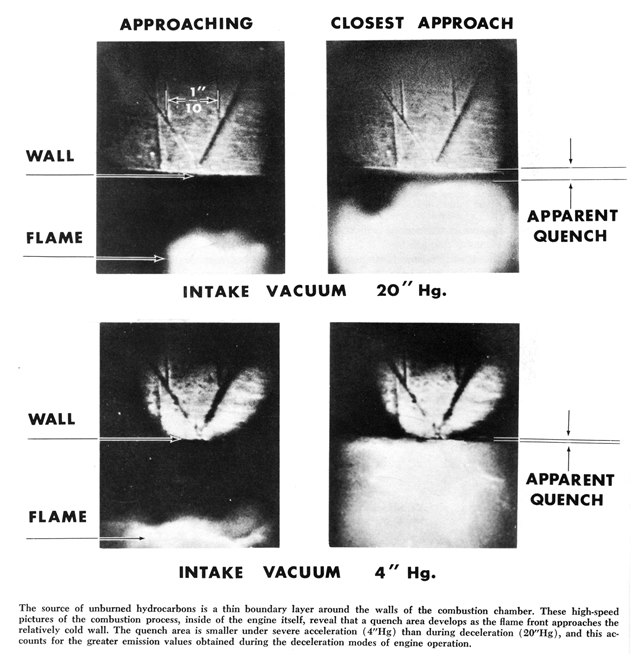
Exhaust emissions of an internal combustion engine consist about one-tenth of one per cent (0.1%) of unburned hydrocarbons. High-speed pictures of the combustion process, taken inside an engine, reveal that the source of these free hydrocarbons is a thin boundary area along the walls of the combustion chamber. When the spark plug ignites the air-fuel mixture, a flame front sweeps across the combustion chamber. When it approaches the relatively cool cylinder walls, a quenching action occurs and the flame front is snuffed out. This leaves the minute quantity of partially unburned air-fuel mixture that is discharged into the atmosphere through the exhaust.
Controlling Exhaust Emissions
Control of exhaust emissions took two forms by 1968: (1) raising the combustion efficiency and (2)
consuming the free hydrocarbons in the exhaust system.
Raising the Combustion Efficiency
Various tests showed that the carburetor's cruising range produced a relatively small quantity of unburned hydrocarbons. However emissions at warm-up, idle, acceleration, and, especially, deceleration left considerable room for improvement. Skinners Union, and Zenith-Stromburg had to develop carbs that more efficiently mixed the fuel and air under these conditions
Combustion Chamber
Cold surfaces within the combustion chamber tend to quench the flame front before all the air-fuel mixture is consumed.
Cooling System
A significant hydrocarbon emission reduction can be achieved by increasing engine operating temperatures.
Systems that consume unburnt hydrocarbons in the exhaust stream can raise operating temperatures. Thus, the addition of the air pump, created a need for improvements to the cooling system. Its no coincidence that the change from down flow radiators to cross flow radiators on cars for the North American Market happened at the same time as the special North American specification. However, the reasons were as much (if not more) for making space for the AIR system as for any potential improvement to cooling efficiency. Another change was from the stamped metal fan to a plastic six blade type.
Carburetor
Higher idle speeds can bring more efficient combustion at idle. Several methods have been devised to keep mechanics from adjusting the idle mixture too rich. I have seen some diagrams that indicate that some sort of tab existed that prevented such a condition on spridgets, but have never actually seen one in person. In addition, because of the way intake vacuums of 20" Hg cause a condition of increased quench area and therefore more hydrocarbon emissions, some later HS2 carburetors had poppet valves fitted to their throttle valves. These poppet valves were designed to open only at 20" Hg.
Ignition Timing
Another method of helping to reduce exhaust emissions is to retard the spark. All manufacturers retarded the ignition timing at idle to make this operating mode more efficient. To compensate, the mechanical advance curve was redesigned to provide a greater advance so that the timing would be more efficient during the normal operation range.
Additional spark advance is required during periods of deceleration to allow as much time as possible for
complete burning of the mixture in the combustion chambers. This was achieved on spridgets with the use of vacuum advance.
Consuming Hydrocarbons in The Exhaust System
We have discussed controlling exhaust emissions by modifying the engine to make it burn the air-fuel mixture more efficiently within the combustion chamber. A second method of attacking this problem is to bum the discharged hydrocarbons after they leave the combustion chamber. Three systems were used on spridgets: (1) the catalytic converter, (2) Exhaust Gas Recirculation, and (3) the Air Injection Reactor (AIR).
Afterburners
The catalytic converter is designed to consume the discharged hydrocarbons by means of heat developed
through a chemical reaction. It was invented by Eugene Houdry who was awarded Patent 2742437 for his invention. Commercially available units began production 1973. The units may be positioned at the muffler or in the exhaust manifold. For the catalytic system, the carburetor and distributor systems needed to be adjusted finely to provide a controlled exhaust stream content that will not smother or starve the chemical reaction. In addition, lead additives in gasoline at the time caused premature failure of the catalytic afterburners. With the advent of EFI, the end of leaded gas, computer controlled engines, and revised standards for oil and fuel additives, is universally installed on new cars in the US. It was also adopted for US market 1500 Midgets. The service life of these units was considerably shorter than more recent examples, and they are no longer available new.
Exhaust Gas Recirculation
On all 1500cc midgets in the North American Market, an Exhaust Gas Recirculation valve rerouted a small amount of exhaust gas into the intake manifold as a way of reducing nitrogen oxide emissions. This valve was controlled by a vacuum pipe connected to the intake manifold and another mechanism prevented its operation unless the choke was completely disengaged. A flame trap prevented damage to the system. However it did require service at 4,000 mile intervals, which was indicated by a warning light activated by a speedometer cable driven counter mounted to the pedal box.
Air Injection Reaction System (AIR)
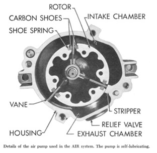
The AIR system consists of an air pump that constantly forces air into each exhaust port immediately after the exhaust valve. Since the exhaust gases at this point are above the kindling temperature and have an excess of hydrocarbons, the infusion of oxygen starts the mixture burning and so consumes the hydrocarbons that normally would be expelled into the atmosphere.
The AIR system draws air from an air cleaner and forces it into a hose, through a check valve, and into an air manifold, where it is delivered to stainless steel nozzles that project into the exhaust ports.
An exhaust check valve is located in the air inlet side of each air supply manifold. It prevents a reverse flow of exhaust gases into the air supply pump in the event that exhaust pressure becomes greater than air pump delivery pressure.
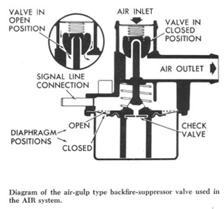
During periods of deceleration, however, a richer mixture results that, not burning completely, discharges into the exhaust manifold. This mixture is leaned out by the pumped air so that the flame of the next firing cylinder travels out of the exhaust port to ignite the mixture, causing a backfire. To prevent this, an air-gulp valve was used which leans out the mixture during high vacuum conditions such as deceleration.
III. Evaporative Losses
Much of the auto smog problem could be traced to mixing of nitrogen oxides from the exhausts of internal
combustion engines and evaporative hydrocarbons from the fuel tanks and carburetors. Evaporative losses
were estimated to be 10-15% of the total hydrocarbons discharged into the atmosphere.
All gas tanks and carburetors were vented to the atmosphere until as late as the 1970 model year. Losses at the carburetor vent occurred almost entirely during the soak period after shutting off a hot engine. The residual heat caused the temperature of the fuel bowl to rise to 150-200°F. ;thus, substantial boiling and vaporization of the fuel occurred. The goal was to limit these losses to 2 grams per hot soak by 1970.
By 1968 Two vapor-control systems were studied: (1) vapor recovery and (2) adsorption-regeneration. In the vapor-recovery system, the fuel tank and carburetor are vented back to the crankcase ventilation system, where the vapor is drawn into the induction system for burning in the combustion chamber. In the adsorption-regeneration system, a canister of activated charcoal traps the vapors and holds them until such time as they can be fed back into the induction system for burning in the combustion chamber. This system needs two valves: a pressure balance valve and a purge control valve. The pressure balance valve opens the carburetor vents to atmospheric pressure during normal engine operation in order to maintain specified metering forces exactly as designed. When the engine is shut down, this valve seals all external vents and routes the hydrocarbon vapors from the carburetor bowl to the canister.
The purge control valve directs a flow of air over the hydrocarbon-laden charcoal in the canister to strip it of the trapped vapors. The vapors are then fed into the intake manifold, to be burned in the combustion chamber during periods of engine operation that would not be affected by the enriched mixture.
On spridgets produced between 1967 and 1974 the absorption-regeneration system is used, however it differs from that previously described as there is no pressure balance valve (with a mixture temperature compensator is employed instead on some applications), or purge control valve. The canister has three connections on top and one on the bottom The connection in the middle on the top is for a purge line which runs to the top of the valve cover via a restricted connection, the remaining two are vapor lines with one running to the fuel expansion tank in the trunk, and the other is connected to the carburetor float bowl vents. The connection on the bottom is for an air vent pipe. The restriction in the connection to the valve cover may well function in leu of a purge control valve.