
The following is taken from the May 1980 issue of Thoroughbred and Classic Cars. Some info may be out of date. I am not the copyright holder and will seek permission or remove this article upon request.
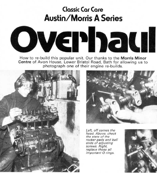

The Austin Morris A Series engine, in 9 or 10 different capacities from 803cc to 1275cc, has powered numerous models from the A30 through Minors of various marks, Sprites, MG Midgets. Minis, 1100s, 1300s, Allegros and so on. Through all its changes and in all its forms it s has retained its basic identity, but many of the parts are not interchangeable, so be careful if you are cannibalising one engine to build another ,
I will try to mention the important differences. but to list them all would lake up something like half this issue of T&CC, so the moral is to check and check again when you are looking for spares, and always take the old part with you.
Having given that warning. it' s only fair to say that the A Series is an easy engine to strip and overhaul, and except for putting in new valve seats, camshaft bearing or cylinder liners it can be done without special tools other than the usual valve spring compressor, piston ring clamp and so on.
Taking the engine out of the car varies with different models so I'll assume that you've drained the oil, taken off the manifolds. starter. dynamo and so on, separated it from the transmission and got it standing in the garage.
Starting at the top, then, take off the rocker cover and the rocker shafts. Here we come across the first differences in models. On early engines there is a locking plate under the nut holding down the right·hand side of the front rocker pedestal. Later engines have four plates, one for each pedestal. Don' t mix these locking plates up, keep them with their pedestals. Some of the rocker studs, the outer ones, also hold the head , so it's a good plan to loosen all the rocker and head studs evenly a little at a time to avoid any chance of head distortion . If you happen to be doing just a rocker overhaul with the engine still in the car, it's essential to drain the coolant and loosen all the nuts or you stand a good chance of letting coolant down into the bores.
Take the rockers off as an assembly, then take out the push rods and keep them in order. I find the easiest way to keep both push rods and valves in order is to put them in holes in a length of wood or even in an upturned cardboard box, and mark one end " front".
To take the rocker assembly apart, lake out the grub screw that holds the front pedestal to the shaft, then take off the split pins and washers from each end and you can slide the rockers, springs and pedestals off. Once again, keep them all in order by threading them on a stiff piece of wire.
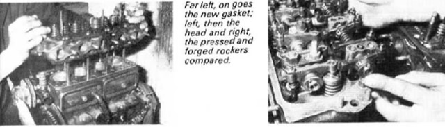
Early engines have forged rockers. but the later ones have rockers of pressed steel which don't look so nice but which do the job just as well and are cheaper to make. The forged rockers can be rebushed if they're worn, but the pressed steel ones can't, so if the bores of these are worn you have to get complete new rockers. These are obtainable, or should be, over the counter at Austin Morris dealers, but if you baulk at the price and can find a good set of forged rockers you can rebush these and use them because the two types are interchangeable but only in sets of eight. You musn't mix forged and pressed steel rockers on the same shaft.
If you are rebushing forged rockers, don't try to press the old bushes out with the new ones. They are thin-wall wrapped bushes, and you'll distort them. Press the old ones out in the vice with a mandrel and a distance tube, and press the new ones in with a smear of oil. The new bushes go in with the join in the wrapped bush at about one o'clock looking at the rocker with the adjusting screw on the right. The bush has an elongated hole to receive the oil from the shaft, so the posit ion isn't all that critical. When you've got the old bush out, look in the bore, and if there's a second, smaller oil hole leading towards the adjusting screw make sure the join in the bush doesn't come opposite this, nor opposite the hole at the top. There aren't holes for these in the bush so you have to drill them from the outside. The outer end of the long hole is sealed by a rivet and after the new bush is in place you drill through this rivet, along the hole and through the wall of the bush with a number 43 drill (2.26mm). Plug the hole at the adjusting screw end with a new rivet. Austin Morris say this river should be held with a spat of weld. but on two occasions when I haven't had welding gear available I've plugged It with a short tapered steel rivet - short enough not to short out into the screwed part, punched It rust below the surface and lightly peened the end of the hole over. In over 20.000 miles. there was no trouble. The second hole to drill is down through the top of the rocker bush. This is a number 47 drill, (1.98mm) and all you have to do is continue the hole in the boss of the rocker through the top wall of the bush. You don't plug this one.
If you can see any signs of ridging In the shaft, or feel any with your fingernail, get a new one. You'll never get quiet tappets with a worn shaft. If the old shaft is serviceable, take the screwed plug out the end and wash it through with paraffin to make sure the oilways are clear. Make sure the plug's tight again, or you'll lose your oil pressure, When you come to fit rebushed rockers you might find they don' t want to go on the shaft because pressing the bushes in has raised a slight burr. The bushes are pre-sized. so they shouldn't need mu ch reaming out. Austin Morris have a special reamer to clear burrs off, but l've found a light touch with a sharp scraper to chamfer the inner ends of the bush slightly is all that's generally needed. In really tight cases I've sent an adjustable reamer through, but with the very lightest of cuts-almost a burnishing rather than a cut.
The ball ends of the adjusting screws should be nicely polished, but if they are worn oval get new ones, and take a close look at the cups on the push rods. II wear has gone through the hardening on these they also need renewing. There are two types of adjusting screw, long ones and short ones. The long ones can be used in any type of rocker, forged or pressed, but the short ones can be used only in forged rockers with a short boss . They fit the others, but there isn't really enough room to get the lock nut on safely, Very often, you find these lock nuts rounded where someone's attacked them with an ill- fining spanner. If yours are like that, get eight new ones. A nut which slips under the spanner when you'r e selling clearances is a nuisance
At the other end of the rocker, the pad which pushes on the top of the valve will show an indentation. This has to be cleaned off to set the tappets properly. It's possible to take out the dent with an oil stone slip if it's not too deep, and I've done it. but if you try this be very careful to keep the sam e curve on the pad as the original. There's a great temptation to stone out the dent and leave a flat, which is all wrong for good valve ope ration . A better plan is to get your local garage to dress the pads up on a proper jig , Several machine tool makers do machines which both face valves and dress rocker pads, but in these days of "if it's worn, throw it away and fit new", not all garages still offer this service. You may have to hunt around. The jig that holds the rocker in the machine locates on the bush, so fit the new bushes first.
Deep indentations can't be dressed out because the grinding goes right through the hardening. When I worked in a garage we used to overcome this by using the arc welder to put a lacing of stellite on the pad before grinding, but whether you'll be able to get this done, and whether the cost of this and a new bush will be more than a new pressed steel rocker I wouldn't like to say.
There shouldn't be any difficulty about taking the valves out , a normal ohv spring compressor will reach, but watch the order in which the parts come off. Some engines have shrouds at the top under the top cap to deflect the oil away from the guides, some have them only on the inlets, and some don't have them at alt. All except Cooper S engines have spring clips on the cotters. and small rubber O-rings in the groove below the valve cotters. You should get new O-rings in you r gasket set, and it's essential to fit new ones to avoid high oil consumption. The old ones harden and aren't fit to use again, Cooper S engines don't have spring clips on the cotters, nor shrouds, nor rubber O-rings. They have double valve springs and rubber seals which fit over the guides.
It isn't easy on paper to give advice about valve stem and guide wear. Some people say a maximum of 3 thou guide wear, others Quote a dial gauge "wobble' reading, but my advice is that If the valve stem shows any sign of ridging scrap it and put in a new guide, If the valve is perfect, but it still wobbles a bit in the guide, fit a new guide. They aren't all that expensive so it's not worth messing about arguing over thous.
The A Series valve guides are a parallel fit in the head , so the old ones can be punched out from the top with a suitable stepped drift. The new guides go in from the top, but as they're parallel with no step you have to watch how far you press them in. There are setting dimensions, but they're not the easies t of things to work to, so before you punch the old guides out cut a piece of tube to fit over the guide so met it comes just flush with the top . Then you use this as a distance gauge when you press the new ones in.
The guides go in with the large chamfer at the top. Old exhaust guides were longer, and had a counterbored part at the bottom to avoid carbon build-up, but Austin Morris found they didn't have to be so long, and shortened them to the same length as the inlets so that inlets and exhaust are now interchangeable. The new short guides fit in the older head s, and stick out from the top just the same amount. Do watch out. though. because at one time the exhaust valves changed stem diameter slightly on some versions of the engine. Be wary if you're replacing only one or two exhaust valves that you get the right diameter. If you can't get them, fit the later valves and later guides.
You can drive the new guides in with the same punch you used to drive the old ones out, but be very careful to start them off dead straight or you'll be in trouble when they're about half an inch in, Better is to use a press, and I find a 9/32 inch diameter bolt in the top of the guide is just the thing to avoid the mandrel of the press damaging the top of the guide. If you do burr the Chamfer a little, take the burr off with a fine file,
With new guides you must reface the seats because however close the manufacturing tolerances, the new guides will never be perfectly concentric with the old seats. I reckon it's worthwhile refacing the seats anyway on a complete overhaul. You can use a hand cutter, though it' s none too easy to get it started on an old hard seat face without chatter. Sometimes a sheet of old newspaper under the cutter gets it going, but don't ask me why. Alternatively, a garage will face both the seats and the valves if you speak nicely to them , After facing, lap the valves in lightly with fine grinding paste, I know the factory doesn't bother, and maybe I'm old-fashioned, but I think it's worth the trouble. If the seats are really bad, new valve inserts can be fitted but as this is a machining job it has to be put out, Your local garage probably doesn't do it these days, but they'II know where to get it done.
Before you do this work it' s as well to check that the faces of the head and block are true. Some people try to slide feeler gauges in between the head and the block, but that doesn't tell you a lot because most of the distortion I've come across is in the middle of the head round the combustion chambers.Clean the block and head faces carefully and check them with a steel straight edge and feelers. Once again it's difficult to be precise, but if you can get more than a 5 thou feeler under the straight edge it' s worth having the face of the head or block skimmed. Tell the machinist you want only the very minimum taken off to get a flat surface. You never know, you might want it done again one day, and it' s nice to have a bit of meat left.
Take a close look at all the studs in the head and the block, and if any are at all suspect take them out with either a stud extractor or two nuts locked on the threads. and lit new ones. A stud that breaks or strips its thread when you're rebuilding is an absolute curse.
I've spent Quite a lot of time on the valve gear and head, and so should you. Getting it right can make the difference between a sweet running quiet engine and a box of old nails. But now, on to the rest of the engine.
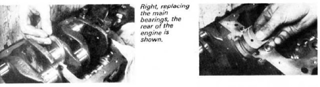
Stripping the rest shouldn't present any problem. The real main bearing caps are sometimes a little tight to get out, but don't terce things. they come eventually. Early engines have castellated nuts and split pins on the mains and big ends. later engines have self locking nuts. If you've got the old type put them back with new split pins, and if you've got self·lockers get new ones. Self -locking nuts don 't lock wit h the same security after they've been used, even once, and the cost of a new set is peanuts compared to that of a thrown rod later on. Crankshaft end float is controlled by thrust washers either side of the centre main. and you should get new ones with a bearing set. If not, ask for them. Watch out for shim packing washers at the nose of the crankshaft . These are to bring the chain wheel exactly into line with the one on the camshaft. If you don't get them in line you' ll have iI very short timing chain life.
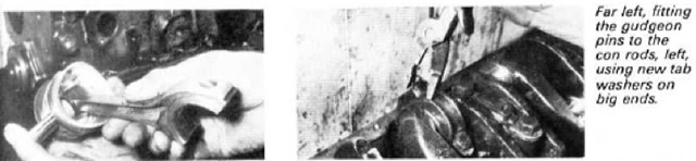
The gudgeon pins are clamped in the small ends of the connecting rods, and the proper way to hold them to undo or do up the screws is to put a bolt in each end of the pin with a head tall enough to stick out beyond the piston. Clamp the se in a vice to hold the pin firm, The pins are a mild interference lit in the pistons, so you will have to warm new pistons slightly to fit them, Once they've been in service they usually push out easily cold,
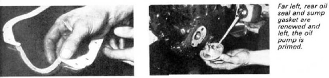
Depending on the age and mark of your engine. the rotor type oil pump which is driven from the back of the camshaft might be made by Hobourn Eaton or Concentric Engineering, and for a short time, because of supply problems, Austin Morris fitted a Burman rotary-vane type . AI! these pumps are interchangeable as units, but the insides are different. There isn' t space here to go into details about overhaul ing the insides of the three types of pump, but as a guide, if there seems to be any wear or slop get a new one. You might be able to get an exchange one. It isn't worth taking a chance where lubrication' s concerned, and unlike pumps met fit in the sump, replacing one on an A Series means having the engine out. Remember that the pump fits with a gasket. For some reason, I've noticed, this isn't always included in an engine overhaul gasket set. It isn' t worth try ing to overhaul the water pump. The complete pumps are available, but some of the pans are not so easy to find.
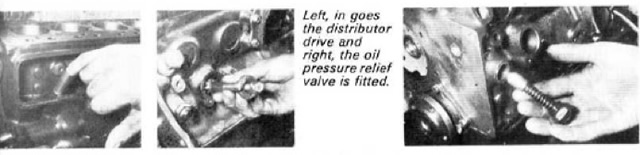
Before the camshaft comes out of the front of the engine you have to take out the cam followers — Austin Morris still call them tappets, and I suppose they' re right — and these must be kept in order. It's unlikely you' ll find much wear on them, but try the fit, just in case, when everything's clean and dry. You can't check a fit property with oil and grease about. You also have to take out the distributor drive spindle, and the easy way to do this is to screw one of the tappet cover holding screws into the end, then it just pulls out with a slight twist as it comes out of engagement with the skew gear on the camshaft . You 'll notice that the end has a slot drive, offset so that there is a large and a small "D". When you come to put the drive spindle back, bring No. 1 piston to top dead centre on its firing stroke. Then set your distributor with the points jus t about to open and the rotor pointing to number one plug lead. If you hold the distributor in a nice convenient position against the engine you can see from the driving dog where you want the large and small "Ds" to be. When you feed the drive spindle in to the camshaft it will turn as the gears engage, so take it out again, turn it the same amount in the opposite direction and push it back in. On most A Series engines, you start to feed the spindle in with the slot vertical and the small "D" to the front of the engine, but that may not be the case on all of them.
The centre and rear camshaft bearings are machined in the block, but unless an oilway's been blocked they don't often wear much. The front one does wear, but this is replacable. The old bearing is pressed out to wards the back of the engine, and the new one pressed in from the front. taking care to get the oil holes lined up with those in the block. It's best done with the special tool which pulls the new bearing in straight. and in any case the bearing has to be reamed dead in line with the other two bearings, so if the bearing is worn, put the job out to an Austin Morris dealer .
There are a number of oversizes for boring the block. and a number of undersizes for grinding the crankshaft . Any Austin Morris dealer will tell you what size pistons and bearing shells are avail able. II another bore would take the block beyond limits you can have it dry linered back 10 standard, and if another regrind would take the crankshaft beyond limits it can be metal sprayed. Most dealers can arrange this for you, if not try one of the engine specialists in T&CC's directory. It's worthwhile getting a new oil pressure relief spring and plunger, and lapping the new plunger into its seat in the block. There's a very handy special tool for this with a rubber end that expands inside the plunger when you turn a handle, and holds it for lapping in. You might be able to borrow one, but if not I've found it can be done with a tight fitting piece 01wood pushed in the end of the plunger. Remember the re are two fibre washers under the cap for the spring.
Take out the old core plugs by punching right through the middle of them with a sharp centre punch, and clean as much of the debris as you can out of the water jackets. Put in the new plugs with a spot of jointing compound and seat them with one firm blow to spread the dome in the housing . Make certain all the oilways in the block and head are clean by squirting paraffin through them with a syringe, and get every thing as spotless as you can. That's half the secret of a successful rebuild. l like to take out all the studs, and countersink the threaded holes lightly. The threads often pull up a little when the studs are put in, and I've known this stop a head gasket from seating property where the stud' s bee n close to a waterway. Dress round the flange of a pressed steel sump, and the pressed steel timing cover, with a hammer and dolly to make sure the faces are flat.Check all the other faces, heater take0" point, thermostat housing and so on, and you're ready to start putting it all tog ether again. There shouldn't be any snags provided you go about things methodically. Reassemble everything with plenty of clean oil. and use new gaskets through out . Except for the core plugs, you shouldn't have to use jointing compound anywhere. An even smear of water pump grease is better, in my opinion, except on Hallite and similar manifold gaskets. and some types of head gasket. which have to be fitted dry, Check the fit of everything as you reassemble, and if something doesn't fit easily find out why in stead of forcing it.

When you come to put the timing wheels on, remember the shims at the front of the crank shaft, and check with a steer rule that the two wheels are dead in line. Fit a new timing chain. The timing marks are two dots, one on each wheel. which have to line up opposite each other, and in a straight line with the centres of the camshaft and crankshaft. This will be when the key in the crankshaft is vertically at the top, and that on the camshaft at about 1 o'clock. Fit the new chain over the wheels, together with the two rubber tensioning rings, one each side of the teeth on the camshaft wheel, and push the wheels and chain tog ether on to the shafts.
There are one or two points at the back of the engine w here you must lake special care to avoid oil leaks. These are the gasket between the oil pump and the block. the gasket between the rear mounting elate and the block, and the soldered join round the pill-box co ver that goes over the oil pump. This soldered joint sometimes weeps, and it's to late to do anything about it with out taking the engine out should oil come through into the bell housing . Take care also with the cork seals that fit in the groove in the sump at the main bearings, When these seals are greased and pressed in their grooves they should poke up about an eighth of an inch at each end. Much more, and they will stop the sump seating properly. much less and the ends won' t seal properly.
Take care over centralising the oil seal in the front timing case cover. Use the crankshaft pulley, with a spot of oil, to get it dead central before you bolt it on the front of the engine,
Depending on the age of your engine, you might have two types of ignition timing mark for the front pulley. The older type has an arrow on the timing case at the top of the pulley to mark top dead centre, and on the later type there is a bracket at the bottom with three pointers. The long one is for top dead centre, and the other two give 5 degrees and 10 degrees advance. The normal timing is 2 degrees advance, static. These marks line up with a notch on the front pulley in each case. Tappet clearances are 0·012 inch, sliding fit with a feeler gauge with the engine cold, both inlet and exhaust.
The main torque ,figures for the A Series engine are;
- Cylinder head and outer rocker shaft brackets, 40lb ft.
- Main bearings with stud nuts, 65lb ft.
- Main bearings with set bolts, 60lb ft.
- Connecting rod big ends, 35lb ft.
- Connecting rod gudgeon pin clamp, 25lb ft.
- Inner rocker shaft bracket nuts, 25lb ft.
- Flywheel attachment bolts, inline engines, 35 to 40lb ft.
- Flywheel centre bolts, transverse engines, 110 to 115lb ft.