
The following was submitted by Brian Morse of the MG Experience's Mg Midget forum
Center Oil Feed Enlargement on a U.S. Spec 1500 Midget Engine
by Brian Morse
I learned of this improvement from two sources: 1)the British Leyland Competition Preparation Manual for the MG Midget 1500, and 2) one of John Twist's Youtube videos discussing the design of the 1500 engine and some of its weaknesses.
Luckily my engine reassembly had just started, so it was easy for me to make this improvement.
Briefly put, the improvement is to enlarge the oil feed holes that lubricate the center main bearing and big end bearings of cylinder #2 and #3 to .3125”. The increased oil flow will better lubricate these parts.
Tools needed:
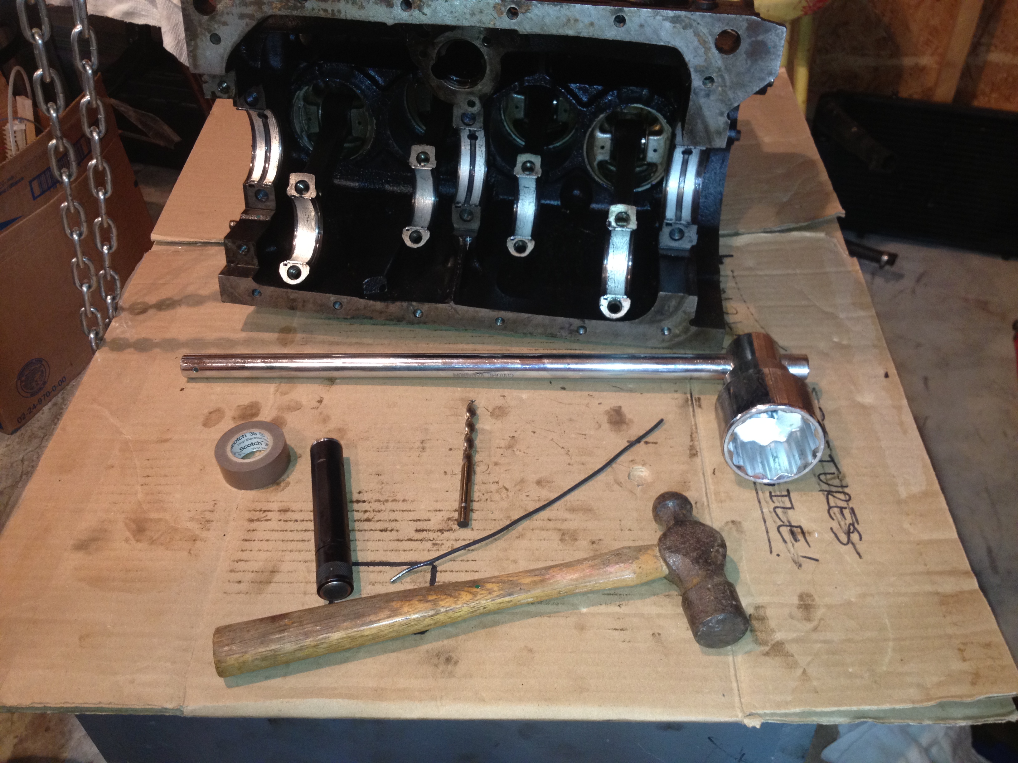
As pictured above, I used a flashlight, some tape, a standard length .3125” drill, my trustyBFH, a piece of 12 AWG solid wire (you can use anything that fits inthe hole and is long enough) and a piece of metal to drive out thedistributor locating sleeve. All I had on hand was my breaker barwhich worked fine. But for added insurance a piece of aluminum orcopper stock would work better. Not pictured and optional is adoughnut shaped magnet
Where to drill:

On the outside ofthe block remove the temperature sensor with a 7/16” wrench. If you peek into the hole with a flash light you will see the firstfeed to enlarge. While you are drilling, be mindful of the threadsthe sensor threads into- you don't want to bung them up with the side of your drill!

Inside the block locate the center main oil feed hole. This is the second spot to drill. Note: If the oil feed hole in your bearing is not already.3125” in diameter you will have to drill the bearing too. I recommend doing so by removing the bearing and placing it in a vice on a drill press or some other method. And don't forget to deburr it!
What to do:
Notethe orientation of the groove on the top of the distributor locating sleeve and be sure it goes back in the same way! Using your metalstock and your hammer, drive out the distributor locating sleeve. Mine came out pretty easy. This is a good time to have your shop helper of choice on the other side of the block to keep the sleeve from flying out and landing on the floor.
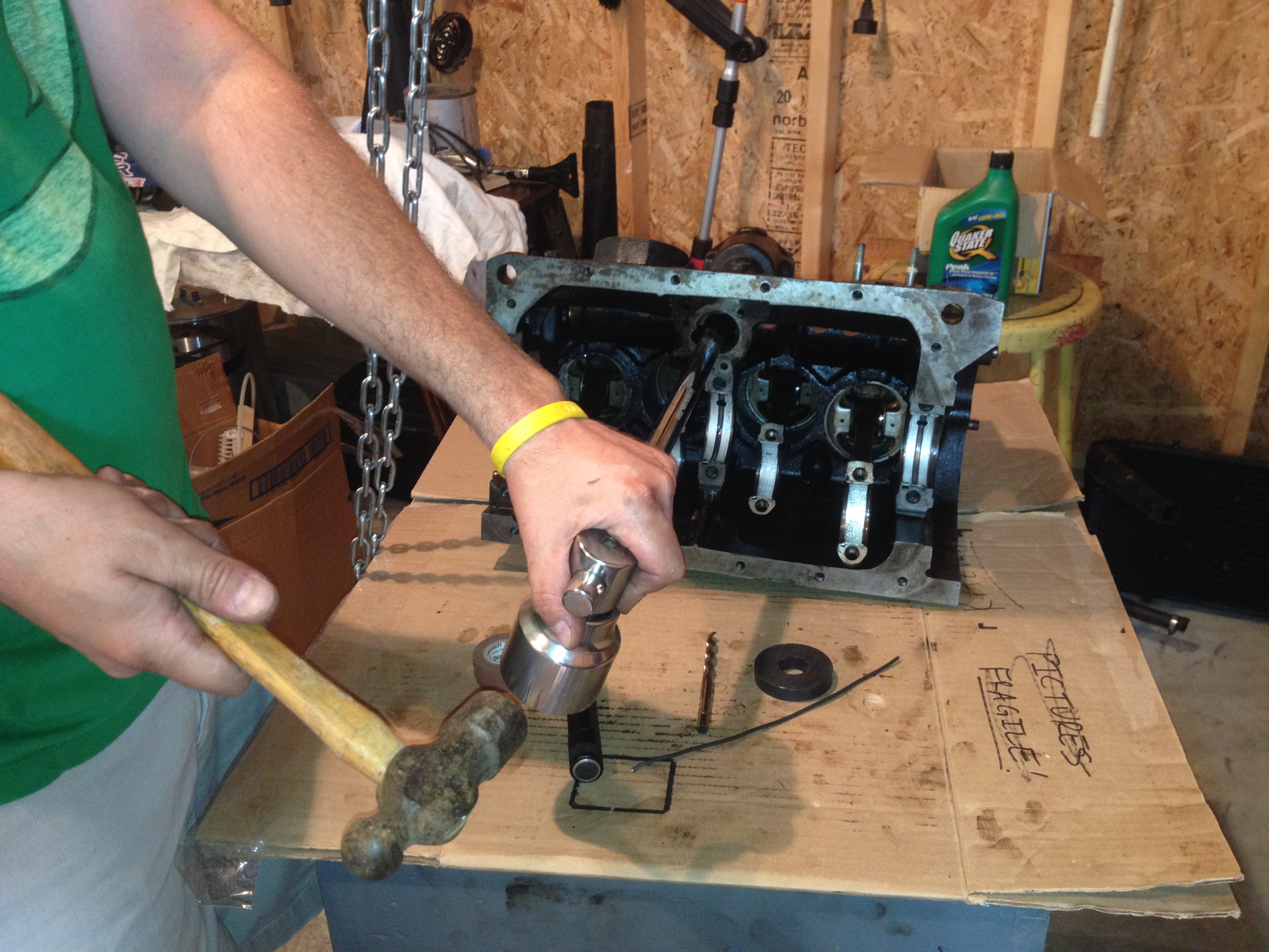
Next use your piece of wire or other measuring device and slide it inuntil it stops at the bottom of the hole. Use your finger to markthe depth of the hole and remove it.
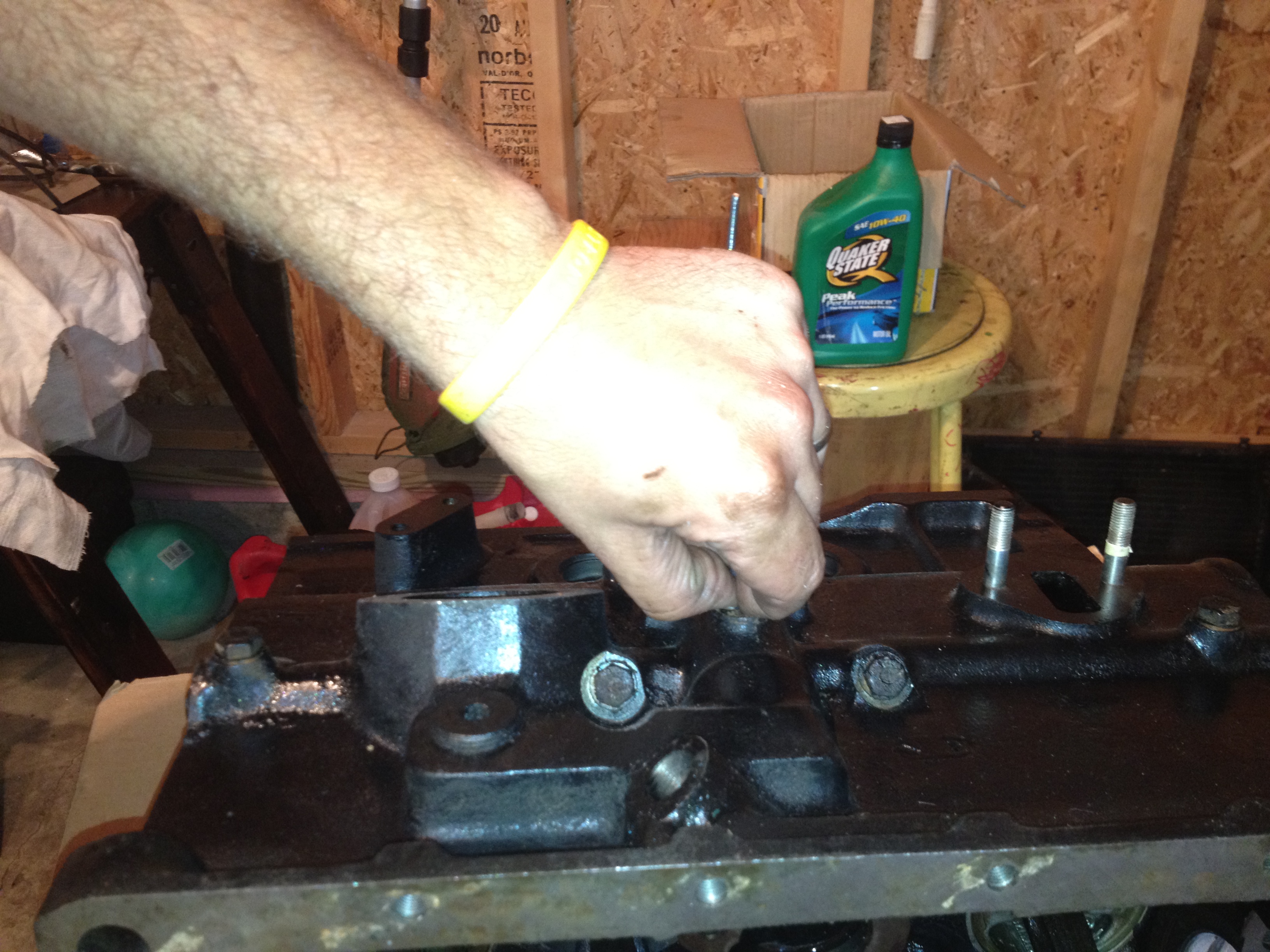
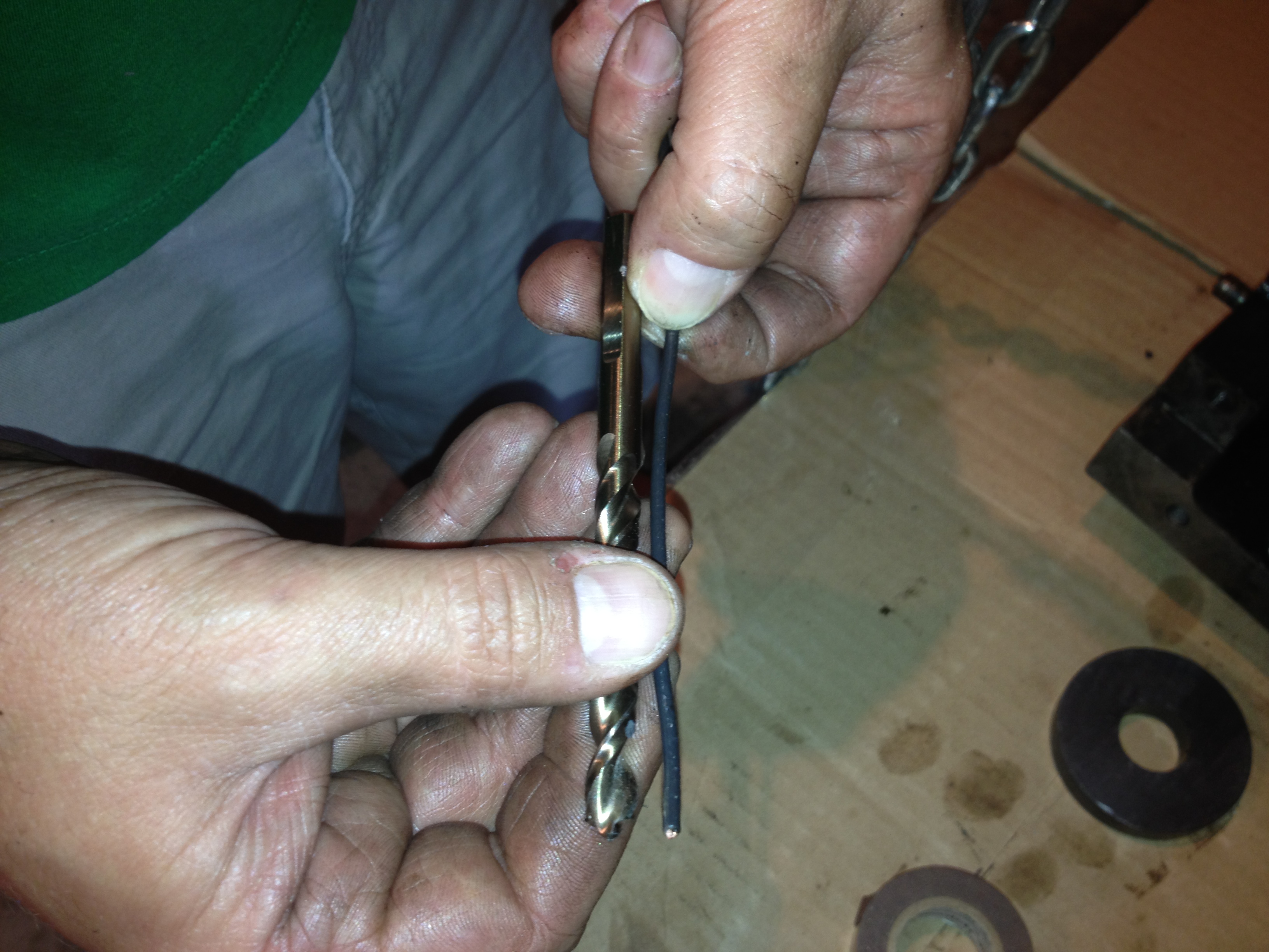
Now transfer that depth to the drill you will be using and mark it with your tape. This is a visual reference to prevent you from drilling too far into the block.
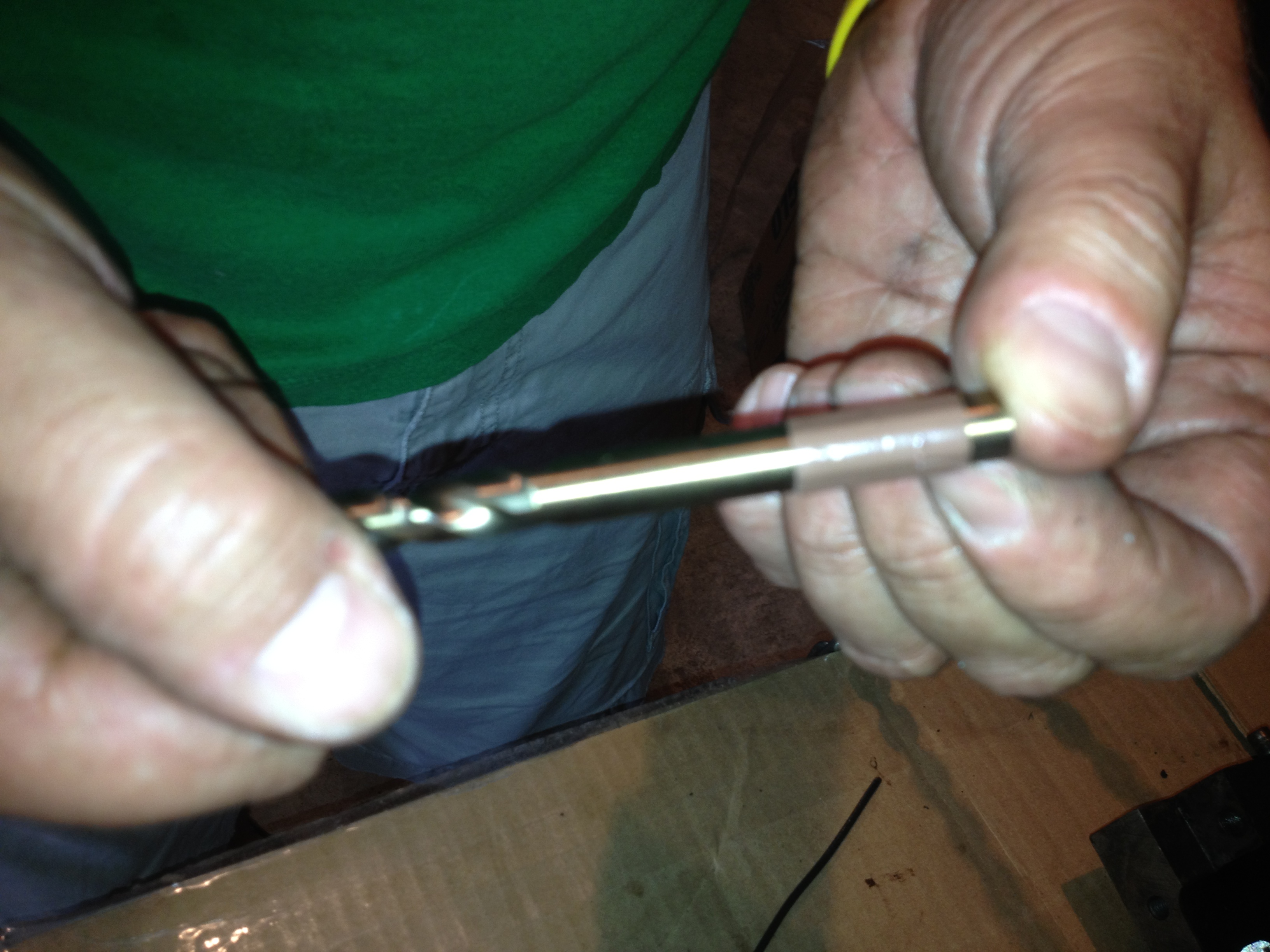
A quick side note on machining cast iron:
For those who haven't done much machining, cast iron by nature is a very tough, very abrasive metal to machine. Therefore it is hard on cutting tools. Also the chips that are made are about the consistency of coarse gunpowder or large grained sand so they get everywhere (that's what the magnet is for).
Also, the part of the drill doing all the work in this operation is the outermost portions of the cutting spurs, which also happens to be the weakest part of the drill
That being said, this is a good time for you to take your time. Don't run your drill at 1,000 RPM and do it dry. Run your drill at a medium-ish speed, use a steady even pressure feeding the drill in and keep it well lubricated. Every 1/4” or so of drill travel pull it out of the block and clear the chips from the flutes on the drill.
Now, if you have one, place your round magnet on the block centered on the hole you will be drilling. This will help keep the cast iron chips from going all over the place. I used regular motor oil as a lubricant. You will know when to stop drilling when you feel the resistance increase while feeding the drill (double check with your tape on the drill).
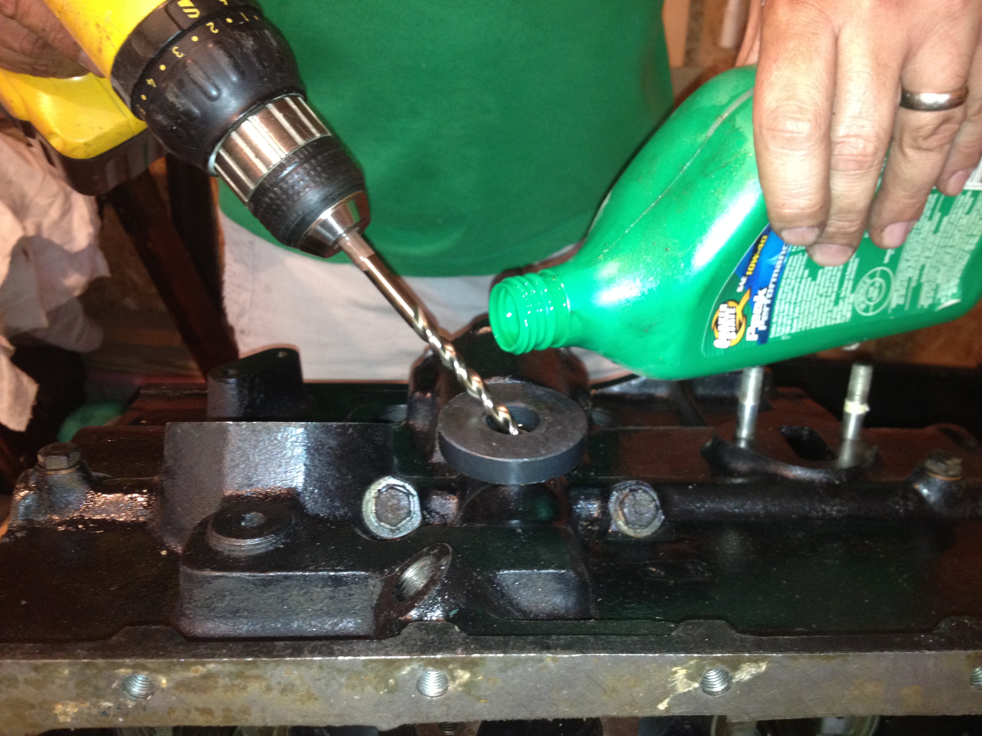
After the first hole is completed, flip the block over and prepare to drill the next hole the same way. The following image shows the approximate angle the drill while machining. I don't show using the magnet in this image, but I did. Also not shown is the bearing was removed and I stuffed rags into the adjacent cylinders to keep debris out.

After you are done machining, it's time to clean up. I used an air hose to blow the holes out from the bearing side out toward the distributor. Check your work with the flash light to make sure the feed holes and the distributor opening are completely clean. Take your time and be meticulous.
Once everything is clean it's time to drive the distributor locating sleeve back in. Make sure it is clean as well. I applied a small amount of engine assembly lube to the portion of the sleeve that goes in first.
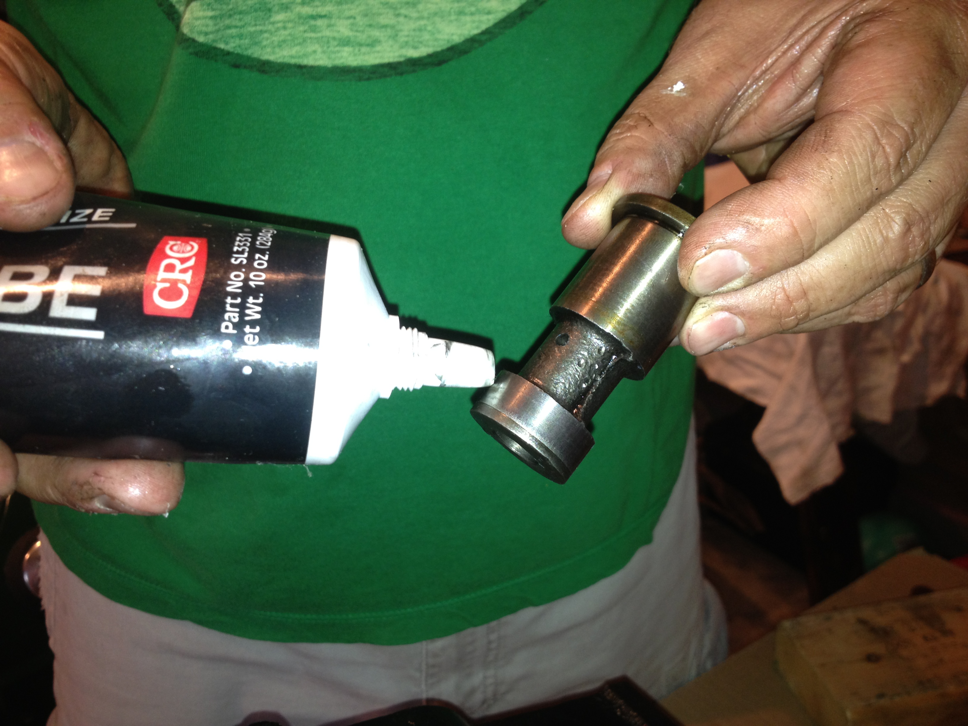
Now start the sleeve into the opening with your hands, no tools allowed yet! It won't go in very far but you want to be sure it is started in line with the bore. Also make sure the groove is the right way.

Now take a small hammer and give it a couple light taps to start it in a bit further. Using your hands, push on it and try to rock it side to side and top to bottom. If you feel it move at all it isn't aligned properly and you need to start over again. Just pull it out and restart it with your hands. If it doesn't move at all you are ready to drive it in with your metal stock and your hammer. Congratulations! You are done!
Now it's time for me to thank those that helped me make this work. First, thanks to my loving wife Amy for being my photographer. Next to Seth Jones for taking the time to touch this up and host it on his website spridgetguru.com. And thanks to the following MG Experience forum members who let me borrow their expertise:
- Hap Waldrop (Speedracer)
- Jeff and Brittany Brackenridge (oldag98)
- Patrick N (Triumphracer)
- Jere McSparran (jmac)
- Glen Phillips (glenp)