
The following was submitted by Jeff Baran of West Bloomfield, Michigan, USA. It was originally featured in a thread on the MG Experience forum.
1972 MG Midget Steering Rack Rebuild
All:
I had recently posted looking for shims for the inner Tie-Rod ends for a 1972 MG Midget. I also realized as I started to dis-assemble that I would need some special tools to accomplish the job.
The reason I started on this adventure first was to clean up the steering rack and make it more presentable, but in doing so, found one side that had a small amount of play.
Since the 1972 models had a steering rack change somewhere during the model year, I found that I had an earlier rack combined with a collapsible steering column. The rack in question shares some parts with an MGA rack as well as I went searching for shims.
The service manual does a fine job of explaining the parts and pieces inside the rack and also defining how to take it apart so I wont go into much detail on any of that, but will show you how I worked around the need for special tools. Some of you may not like what I did, but the method seems to have worked fine. The information below is what I did , and if you choose to try and follow this method, you do so at your own risk, etc. It is just an option I thought I would share.
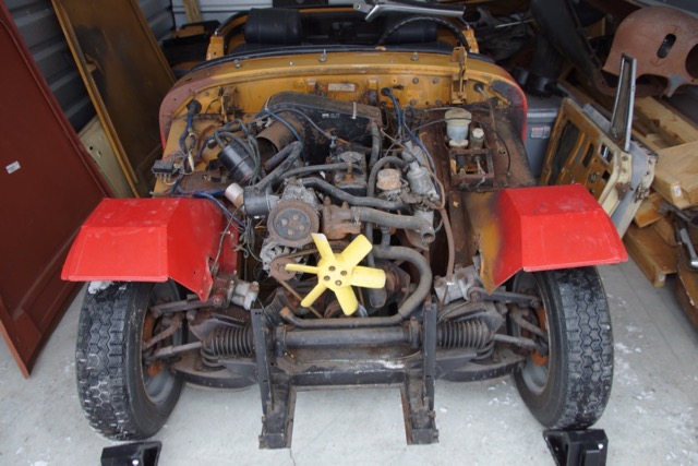
Here is a photo of my Rack still installed on the car. Not in terrible shape, but boots were cracked, full of grease, etc. It definitely needed some TLC.
After removing the rack and disassembling the outer tie rod ends and removing the Boots, the inner Tie rod ends can be removed. The way these work, which is different than the later racks and also different than the MGB racks is that the whole Tie rod assembly threads into the Rack with a lock washer. You can purchase complete Tie rod assemblies from Moss and probably others as well. I wasn’t looking to do that as they cost more than a re-furbed rack complete so I didn’t research it much further. There is a lock washer that is trapped between the Tie-rod assembly and the Rack when bolted together that in theory is supposed to allow the tie-rod to be taken apart in pieces as opposed to a complete assembly. The Bentley manual warns that this lock washer may not retain the socket portion of the tie rod during assembly and the whole assembly may come off and then you need the special tools (Pictures in the Bentley manual) to dis-assemble. That is exactly what happened to me. The tools are essentially a C-Spanner and a Pin Spanner.
There were some on mgaguru.com at some point in time for sale, but no longer available.
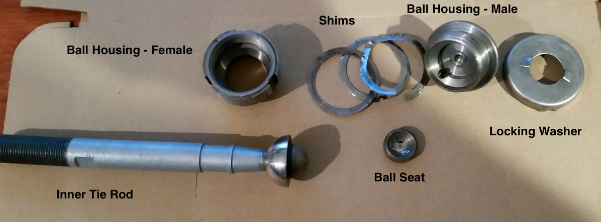
Fast forward to looking at the complete Tie-rod assembly. Hopefully this looks familiar. You can ID the parts from the various websites for their official names., and I’ve included a photo of the dis-assembled parts labeled for convenience.
Complete Tie Rod Assembly:
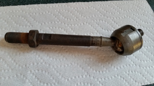
Although maybe a little difficult to see, but there are shims between the female and male portions of the actual socket that set the freeplay or tension on the ball/socket joint. I could not find a spec. Mine were floppy and one actual had some axial end play. That is what I was trying to solve.
Here is the labeled picture:

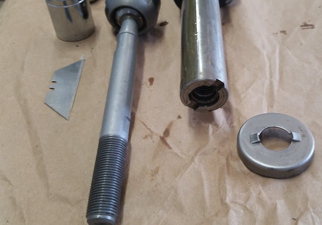
To take a quick step back, here is a picture of the Lock washer in place that engages into a slot at the end of the rack, and then gets peened into the grooves on the ball socket to keep the whole assembly in place.

When you remove the lock washer you can see 2 holes that are used with the Pin Spanner tool (I didn’t have one of those) and the grooves or slots in the outer housing are for the C-Spanner tool (I did’t have one of those either, although I think there are adjustable ones available.

After looking at pictures of the tools, and watching a John Swift video taking apart an MGB tie-rod, I convinced myself I could tackle this with channel locks and welding up a “pin spanner”. But before I did that, I looked for a way to avoid the welding. I have a little flux welder, but my skills are not great, so I set off to the hardware store to find some parts and pieces.
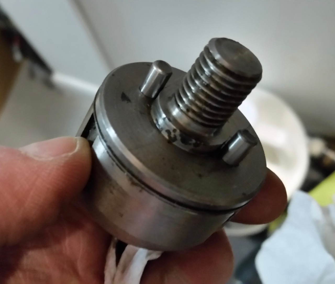
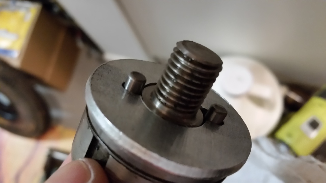
In my visit to the store, I found a 5/8 “ washer, a 7/16 inch washer, and 3/16 - ½ inch long dowel pins that fit the pin holes. The larger washer fit over the shoulder on the male ball housing and the 7/16 washer had a nice fit over the threaded portion. Special note that during re-assembly I found that the ½ inch long pins were just a bit too long, so I ground them down a slight amount. They end up contacting a small portion of the ball seat inside the housing and could have an influence on selecting the shims correctly.
I was also looking for a nut to fit the shaft and realized it is a ½ x 16 thread. Not a common thread, so I would need to use the actual rack to thread into.
I used the 5/8 inch washer to make a double keyhole configuration allowing the washer to fit over the shoulder and the pins. The pins were so close to the shoulder that drilling them as a hole in the washer was a challenge. I didn’t have access to a drill press so I drilled as best I could and then used a round file of the proper size to make the keyholes.
Here are a couple of pictures of the male ball housing with the pins and keyhole washer in place. The purpose of the washer is to help support the pins and fill the gap between the shoulder and the base of the tie-rod end.
 |
 |
|---|---|
I was going to then add a piece and weld the pins to it, but I thought I would give it a try by just adding in the piece and then threading the rack on to hold everything together.
I used a piece of aluminum I had laying around to try the concept (Much easier to drill. I did end up switching to a piece of steel (I had some angle Iron around that worked much better as the parts were torqued quite well with some corrosion requiring quite a bit of torque to remove. The aluminum worked fine on one side, but on the other, it started to deform.
Here is a pic of the aluminum arm I used (substitute steel for additional strength):
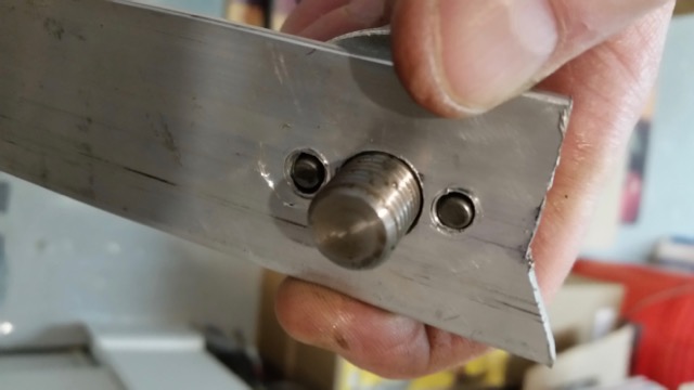
I then placed the 7/16 washer (Nice fit over the ½ inch thread). I test fit at the store as not all of them would fit.
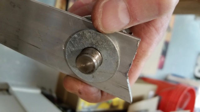
I then threaded this into the end of the Steering rack to just clamp everything together. It was not extremely tight, just enough to clamp everything together. I went to utilize the channel lock pliers and realized that was not going to be successful. These were tighter than what I could grip with channel locks. I ended up using a small pipe wrench, which actually worked quite well as I could pretty much grip into the slots on the outer housing.
Here you can see it in place. With said pipe wrench positioned, I was able to loosen the assembly.
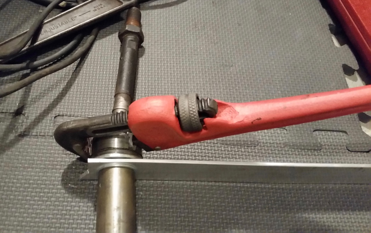
As mentioned above, the first one I did, the aluminum worked fine, the second one I had to switch over to steel. It was much tighter and the aluminum was deforming.
With the parts dis-assembled, I was able to check for wear and didn’t really see any, but will re-shim and re-assemble and see how it goes. I have some shims on order. I finally found them in the Moss catalogue under the MGA rack. They come in 3 different sizes. I measured what I had for shims. One of mine was at 0.013 in total, the other was at 0.022 in total. Some of the 0.003 in shms that were on mine were deformed during removal, so if you do this, expect to replace all the shims. Maybe some can be saved, but probably not all of them. The 0.003 in size is pretty weak.
Here are the part numbers in case anyone wants them for reference. If you google, they will come up on many sites. I could never find them though in a listing for the Midget. I sure hope they work. (Update on the Shims that were supplied. They were made of Mylar. I ended up using some of them along with some of the original steel shims. They tightened up well and the Lock washers will keep everything in place.
.003 in shim - 262-130
.005 in shim - 262-140
.010 in. shim - 262-150
I proceeded to clean up the rack. It was not well maintained. Had grease put in it as some point, so I cleaned all of that out, polished up the rack itself. There was some minor corrosion and rust inside. I gave everything a coat of primer and painted things up. Still waiting for the shims and new boots, etc, to finish up this project.
Again, here is a photo of what the inner workings of the tie-rod assembly look like. You can see where one of the thin shims is mangled. There was obviously some corrosion causing it to stick and then when I loosened it, came out like an accordion.
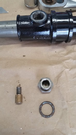
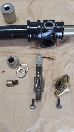
Here are a couple of more photos of the pinion gear and various parts of the rack assembly. I applied some of the 90 wt. gear oil as I went. I figured it would be easier than trying to fill a completely dry rack all at once.
 |
 |
|---|---|
| Right Side Damper: | Left Side Damper and Pinion Gear: |
Here is the Lock washer and the end of the rack that the tabs engage in:
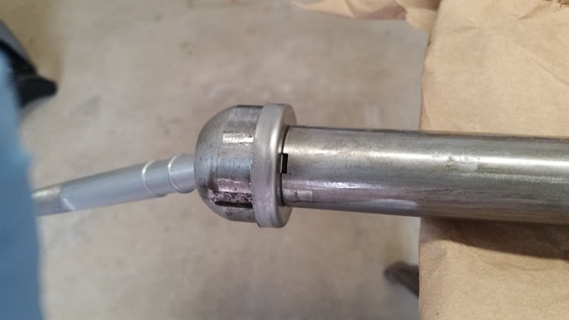
Here is the Tie-Rod assembly in place with the washer (Note I had not yet peened the washer into the slots on the Female Ball Housing – Don’t forget to do this):
Some Photos of the Right and Left Boots in place along with the Dampers and pinion gear assembled:
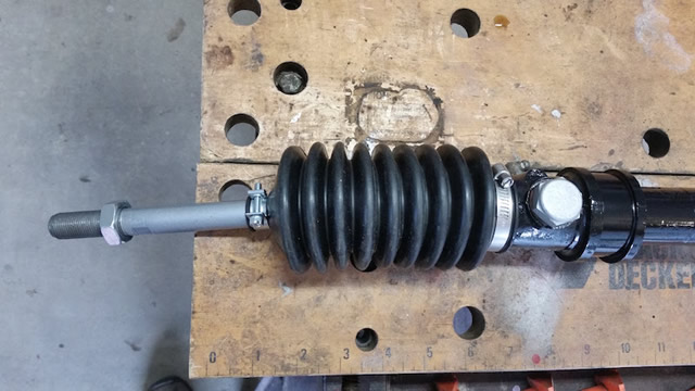
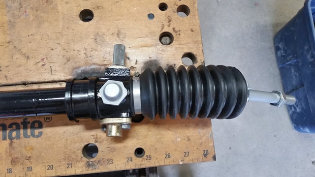
Finally the completed rack assembly:
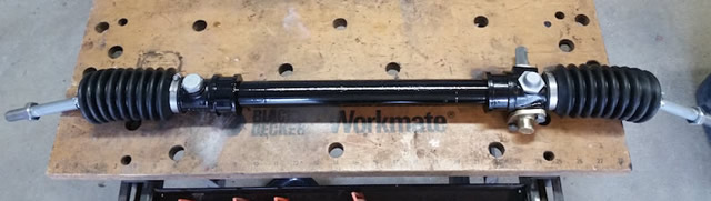
I Still need to find a seal for the pinion shaft. The original was leaking and the rubber hardened and brittle. These are no longer available that I can find so I will try and make up a substitute. I have a felt washer in place not, but not properly retained.
Hope this helps anyone that might want to tackle a re-build or read this and realize that you don’t want give it a go.
Jeff